Difference between revisions of "2015 DOCK tutorial with Poly(ADP-ribose) polymerase (PARP)"
Stonybrook (talk | contribs) (→Grid computing) |
Stonybrook (talk | contribs) (→Grid computing) |
||
| Line 207: | Line 207: | ||
=== Grid computing=== | === Grid computing=== | ||
| − | In order to save computational resources and speed up the docking process, we let dock to pre-calculate the potential energy around the docking region which defined by previous section before we perform docking calculation. | + | In order to save computational resources and speed up the docking process, we let dock to pre-calculate the potential energy around the docking region, which defined by previous section, before we perform docking calculation. |
In grid program, there are two ways to evaluate the potential energy in docking region: contact and energy scoring. The users could apply these two method independently to their docking system by simply typing “yes/no” in the input file grid.in. Once finished, the grid results will be saved in the corresponding extension file: *.cnt and *.nrg. Another important parameter in grid program is bump grid. This variable determines the degree of overlapping among atoms in receptor. The usage method is same as contact or energy scoring. | In grid program, there are two ways to evaluate the potential energy in docking region: contact and energy scoring. The users could apply these two method independently to their docking system by simply typing “yes/no” in the input file grid.in. Once finished, the grid results will be saved in the corresponding extension file: *.cnt and *.nrg. Another important parameter in grid program is bump grid. This variable determines the degree of overlapping among atoms in receptor. The usage method is same as contact or energy scoring. | ||
Revision as of 17:55, 4 March 2015
For additional Rizzo Lab tutorials see DOCK Tutorials. Use this link Wiki Formatting as a reference for editing the wiki. This tutorial was developed collaboratively by the AMS 536 class of 2014, using DOCK v6.6.
Contents
I. Introduction
DOCK
DOCK is a molecular docking program used in drug discovery. It was developed by Irwin D. Kuntz, Jr. and colleagues at UCSF (see UCSF DOCK). This program, given a protein binding site and a small molecule, tries to predict the correct binding mode of the small molecule in the binding site, and the associated binding energy. Small molecules with highly favorable binding energies could be new drug leads. This makes DOCK a valuable drug discovery tool. DOCK is typically used to screen massive libraries of millions of compounds against a protein to isolate potential drug leads. These leads are then further studied, and could eventually result in a new, marketable drug. DOCK works well as a screening procedure for generating leads, but is not currently as useful for optimization of those leads.
DOCK 6 uses an incremental construction algorithm called anchor and grow. It is described by a three-step process:
- Rigid portion of ligand (anchor) is docked by geometric methods.
- Non-rigid segments added in layers; energy minimized.
- The resulting configurations are 'pruned' and energy re-minimized, yielding the docked configurations.
Poly ADP Ribose Polymerase (PARP)
Poly (ADP-ribose) polymerase (PARP) is a family of proteins involved in a number of cellular processes involving mainly DNA repair and programmed cell death. (Wikipedia: http://en.wikipedia.org/wiki/Poly_ADP_ribose_polymerase) The particular PARP family member we will focus on is PARP5b (aka: Tankyrase 2) of which the catalytic domains contains 227 amino acid residues. Olaparib (AZD-2281, trade name Lynparza) is an FDA-approved chemotherapeutic agent, developed by KuDOS Pharmaceuticals and later by AstraZeneca. It is an inhibitor of poly ADP ribose polymerase (PARP), an enzyme involved in DNA repair.[1] It acts against cancers in people with hereditary BRCA1 or BRCA2 mutations, which includes many ovarian, breast, and prostate cancers. (Wikipedia: http://en.wikipedia.org/wiki/Olaparib)
In this class, we will perform docking experiments and virtual screening on a crystallographic structure of PARP5b in complex with a small-molecule inhibitor, olaparib (PDB ID: 4TKG).
Organizing Directories
While performing docking, it is convenient to adopt a standard directory structure / naming scheme, so that files are easy to find / identify. For this tutorial, we will use something similar to the following:
~username/AMS536/dock-tutorial/00.files/
                              /01.dockprep/
                              /02.surface-spheres/
                              /03.box-grid/
                              /04.dock/
                              /05.mini-virtual-screen/
                              /06.virtual-screen/
In addition, most of the important files that are derived from the original crystal structure will be given a prefix that is the same as the PDB code, '4TKG'. The following sections in this tutorial will adhere to this directory structure/naming scheme.
II. Preparing the Receptor and Ligand
Go to the Protein Databank Website (pdb.org) and search for 4TKG. This is the code for PARP protein crystal structure in complex with olaparib. Download the PDB (text) file for this protein. You will then want go to your /00.files directory and copy this file using the command below.
cp ~/Downloads/4TKG.pdb ./
And then we will create 4 files in 01.dockprep/ directory:
 4TKG.dockprep.mol2
 4TKG.lig.mol2
 4TKG.rec.mol2
 4TKG.rec.noH.pdb
Create the dockprep file
To create a temp.pdb file, you will first need to open 4TKG.pdb in Chimera. You will notice that there are four copies of this protein-ligand complex in the original crystal structure. Since we only want to work with one of these, select 'Chain A' (select->chain->A). Once Chain A is selected we will invert the selection by going the the 'Select' tab->invert(all models). Next we will delete these chains by going to the 'Actions' tab->atoms/bonds->delete. Save this file as temp.pdb in your 00.files directory.
For the "4TKG.dockprep.mol2" file: open the temp.pdb in Chimera; delete the water molecules. In order to prepare your file for docking you will want to follow this workflow "Tools->Surface/Binding Analysis->Dock Prep". Use all of the default settings and select charge model AMBER ff14SB. Save this file as 4TKG.dockprep.mol2 in your 01.dockprep directory.
Next, we will want to make the ligand file. To accomplish this, you will open your 4TKG.dockprep.mol2 file in Chimera. Select the ligand and 'invert selection' as before. You can then proceed to delete everything except the ligand. Save this as 4TKG.lig.mol2 in your 01.dockprep directory.
Once again, open up the 4TKG.dockprep.mol2 file in Chimera. Select the ligand and delete it. Save this as 4TKG.rec.mol2. From here select all the hydrogens and delete them. Save this as 4TKG.rec.noH.pdb.
III. Generating Receptor Surface and Spheres
Generating the Receptor Surface
Xingyu
Placing Spheres
Sphgen is a program that generate sets of overlapping spheres that define the shape of a molecule or molecular surface. Spheres are generated over the entire receptor and ligand surface. For further information on how Sphgen functions, please refer to the latest version of the DOCK manual:
<http://dock.compbio.ucsf.edu/DOCK_6/dock6_manual.htm>
To generate spheres using Sphgen follow the steps below:
Step 1. Create an input file name INSPH with the following information:
vim INSPH
4TKG.rec.dms #surface file generated above will be the input file
R            #flag to place spheres outside (R) or inside (L) of the surface
X            #flag that informs sphgen of the subset of surface points to be used (X = all points)
0.0          #flag that prevent the generation of large spheres with close surface contacts(default= 0)
4.0          #maximum radius of the spheres generated (default = 4.0 Angstroms)
1.4          #minimum radius of the spheres generated (default = radius of probe)
4TKG.rec.sph #this will be the file which contained the clustered spheres generated
Step 2. Run the program Sphgen using the command sphgen:
sphgen -i INSPH -o OUTSPH
-i is the flag that give sphgen the input file INSPH
INSPH is the file created above that gives sphgen instructions
-o is the flag to create the oputput file
OUTSPH is the output file with the information of the spheres generated from sphgen
Step 3. Visualization of the spheres generated:
Visualization of the spheres can be done directly with chimera or with the program showsphere
3 a. Visualization directly with Chimera:
- Launch Chimera, choose File -> Open, choose 4TKG.rec.mol2
- choose File -> Open, choose 4TKG.rec.sph
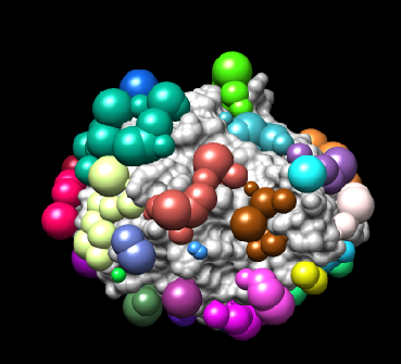
You should have an image like this:
3 b. Visualization with showsphere:
showsphere convert the .sph file into PDB format.
(i) Run showsphere, by typing showsphere into the terminal:
showsphere
You will be prompted with the following questions:
Enter name of sphere cluster file:
     4TKG.rec.sph
Enter cluster number to process (<0 = all):
     -1
Generate surfaces as well as pdb files (<N>/Y)?
     N
Enter name for output file prefix:
     output_spheres
Process cluster 0 (contains ALL spheres) (<N>/Y)?
     N
-1 is a flag that allow you to see all possible spheres
(ii) Open Chimera
- Launch Chimera, choose File -> Open, choose 4TKG.rec.noH.pdb
- Go File -> Open, choose output_spheres.pdb
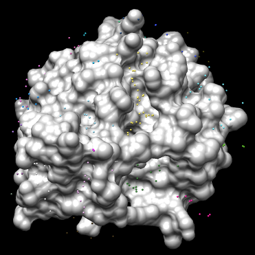
You should see many spheres placed all over the receptor surface.
Step 4. Selecting spheres of interest:
To select spheres of interest you need to run a program name sphere_selector in the terminal. The idea is to allow the program to select spheres that are within a user-defined radius (in this case, 8.0 angstroms) of a target molecule or a known binding site:
sphere_selector 4TKG.rec.sph ../01.dockprep/4TKG.lig.mol2 8.0
A new file name selected_spheres.sph will be generated.
Step 5. Visualize the spheres using showsphere as previously done:
showsphere
When prompted on the command line, answering the questions as follows:
Enter name of sphere cluster file:
     selected_spheres.sph
Enter cluster number to process (<0 = all):
     -1
Generate surfaces as well as pdb files (<N>/Y)?
     N
Enter name for output file prefix:
     output_spheres_selected
Process cluster 0 (contains ALL spheres) (<N>/Y)?
     N
View spheres in Chimera:
- Launch Chimera, choose File -> Open, choose 4TKG.rec.noH.pdb
- Go File -> Open, choosing output_spheres_selected.pdb
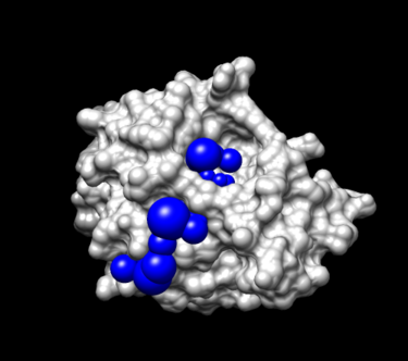
- Go Select -> Residue -> SPH
- Go, Actions -> Atoms/Bonds -> sphere
IV. Generating Box and Grid
Box Generation
- Make a new directory and name it: 03.box-grid/
mkdir 03.box-grid
- Make a new file in this directory and name it showbox.in
vim showbox.in
- This will automatically open the file showbox.in. Edit the file showbox.in as follows:
   Y                                               # Yes, generate a box
   8.0                                             # Size of the box in Angstroms
   ../02.surface-spheres/selected_spheres.sph      # Sphere.sph file
   1                                               # Cluster number
   4TKG.box.pdb                                    # Name of the output file
- Save the file using the command:
:wq
- Run the command:
showbox < showbox.in
Cong Liu
Grid computing
In order to save computational resources and speed up the docking process, we let dock to pre-calculate the potential energy around the docking region, which defined by previous section, before we perform docking calculation.
In grid program, there are two ways to evaluate the potential energy in docking region: contact and energy scoring. The users could apply these two method independently to their docking system by simply typing “yes/no” in the input file grid.in. Once finished, the grid results will be saved in the corresponding extension file: *.cnt and *.nrg. Another important parameter in grid program is bump grid. This variable determines the degree of overlapping among atoms in receptor. The usage method is same as contact or energy scoring.
In this tutorial, we just use the energy scoring option to evaluate the potential energy in docking region. Mathematically grid use the empirical London-Jone's model and Coulomb electrostatic interaction function to approximate the potential energy in each grid points. The coefficient for electrostatic interaction is fixed. However, you could specify the exponent order for vdw interaction calculation(a and b) by setting the attractive_exponent and repulsive_exponent variable value. Other coefficients in London-Jone model are specified by the vdw_AMBER_parm99.defn file.
In practice, you have two ways to calculate the grid.
The more clear and efficient way:
- Create the grid input file:
vi grid.in
- Setting all variables in grid.in. And run the program:
grid -i grid.in
A more interactive and user friendly way:
- Run the grid program
grid
Then follow the instruction of the program and setting all variables by answering each questions. If it were you first time to run dock, we strongly recommend you to use second method. For this tutorial, we summarize all parameters that will be needed and give a brief description.
| Parameter | Value | Description |
|---|---|---|
| compute_grids | yes | compute scoring grids (yes) |
| grid_spacing | 0.4 | distance between grid points along each axis (in Å). |
| output_molecule | no | write up coordinates of the receptor into a new file |
| contact_score | no | compute contact grid? default is no |
| energy_score | yes | compute energy score? yes - we are using this method to compute force fields on probes |
| energy_cutoff_distance | 9999 | the max distance between atoms for the energy contribution to be computed |
| atom_model | a | atom_model u means united atom model where atoms are attached to hydrogens, and a stands for all-atom model, where hydrogens on carbons are treated separately |
| attractive_exponent | 6 | attractive component stands for exponent of the attractive LJ term in VDW potential |
| repulsive_exponent | 9 | repulsive component stands for exponent in the repulsive LJ term in VDW potential |
| distance_dielectric | yes | distance dielectric stands for the dielectric constant to be linearly dependent on distance |
| dielectric_factor | 4 | distance dielectric factor is the coefficient of the dielectric |
| bump_filter | yes | bump filter flag determines if we want to screen orientation for clashes before scoring and minimization |
| bump_overlap | 0.75 | bump_overlap stands for the fraction of allowed overlap among receptor's atoms where 1 corresponds to no allowed overlap and 0 corresponds to full overlap being permitted. |
| receptor_file | ../01.dockprep/4TKG.receptor.mol2 | our receptor file |
| box_file | 4TKG.box.pdb | the box file we generated in the Box section |
| vdw_definition_file | ../zzz.parameters/vdw_AMBER_parm99.defn | van der Waals parameters file |
| score_grid_prefix | grid | prefix for the grid file name; all the extensions will be generated automatically. |
More detail, please refer to:
http://dock.compbio.ucsf.edu/DOCK_6/tutorials/grid_generation/generating_grid.html
http://dock.compbio.ucsf.edu/DOCK_6/dock6_manual.htm#GridOverview
V. Docking a Single Molecule for Pose Reproduction
Rigid docking
Rigid docking is a method that is used to dock a ligand to it's receptor without changing the internal conformations of the molecule, but rather as inflexible, rigid molecules. This is much faster than flexible docking and is used in cases where the ligand molecule has too many rotatable bonds.
In order to run rigid docking on dock 6, you must first create an input file:
touch -i rgd.in
VI. Virtual Screening
george jones
Sam Chiappone
