2023 DOCK tutorial 1 with PDBID 4S0V
Contents
Introduction
This tutorial will walk you through the steps necessary for using the DOCK software package. Many drugs are small molecular compounds that attach, or bind, to a protein in our bodies to change how that protein functions. By changing the function of a protein we can treat disease and help people manage symptoms of disorders. Traditionally drug discovery was done through a type of "trial and error" process called High Throughput Screening. Scientists would chemically make, or buy, thousands of small compounds and expose them to cells. They would then observe how the cells responded, either favorably/unfavorably/no effect. This method is time consuming and expensive. It would be better if the scientific community could "virtually screen" these molecules using a computer before creating/buying them - thereby focusing the cost and effort on those which showed the most promising computational results. The DOCK software brings this drug discovery process into the 21st century and uses computers to bind these small molecular compounds to a protein and evaluate the results. DOCK uses algorithms to bring together the small molecule, known as the ligand, and the larger protein, and "DOCK" them together. Our tutorial will walk you through preparing a protein and ligand for docking using an example complex from the protein data bank (https://www.rcsb.org/), complex # 4S0V.
The following steps will be followed:
- Setting up your environment
- Downloading a protein from the PDB database
- Determining if there are any missing loops in the structure and if they need to be modeled
- Preparing the ligand
- Preparing the protein
- Finding the binding site of the protein
You will need certain skills to successfully complete this tutorial. This website has tutorials for the following:
This tutorial will be using PDB#4S0V as an example. Keep in mind that when you work on your own project to replace any reference to 4S0V with your own protein number.
Learning Objectives
- Understand why DOCK was created and its current role in drug design
- Gain the ability perform virtual screening of small molecular compounds to a protein from the Protein Data Base (https://www.rcsb.org/)
Setting Up Your Environment
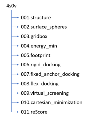
Before we get started working with molecules it's a good idea to set up your directory structure on Seawulf to keep everything organized. The following directory structure should be created:
Downloading a protein from the PDB database
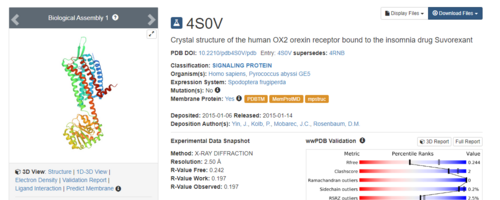
The first step is to download a protein complex from the PDB. As mentioned, this tutorial will be using #4S0V throughout. On the right side of the top banner you will see a search bar:
.Simply type in 4S0V and press enter. The resulting protein complex will be displayed.
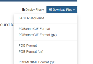
On the right hand side, click on Download Files, then choose PDB Format.
That's it! The pdb file is now saved to your local computer.
Preparation of the ligand and protein
The following steps will show you how to prepare the protein and ligand structures to be used with DOCK. All steps in this section will be done using Chimera. These steps are very important - if your initial structure is not prepared properly, all downstream analysis can potentially be incorrect. This section will show you how to:
- Evaluate the structure to determine if there are any missing loops
- Prepare the protein structure
- Prepare the ligand structure
Evaluating the Structure
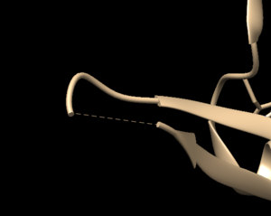
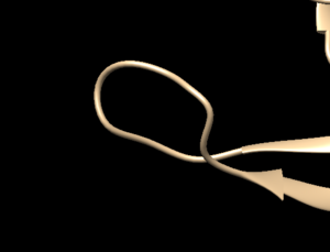
Open the previously downloaded .pdb file into Chimera. The first thing you want to look for are missing loops. A missing loop will be indicated by a dashed line in the structure:
The first decision you'll need to make is if these missing loops are important in your model. This decision is made by determining if the missing loop is close to the binding site. If it is far enough away, it probably won't affect the dynamics of the protein/ligand interaction and can be left alone. If the missing section is close to the binding site, you may want to fix it to more accurately model the binding site and the protein/ligand interaction.
To determine the distance between the missing loop and the binding site:
- Select an atom at near the start of the missing section (hold the ctrl button while clicking it)
- Select another atom near the binding site (hold ctrl + shift while clicking the second atom)
- Go to Tools → Structure Analysis → Distances
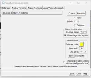
A dialogue box will appear:
Click the 'create' button and the distances between the two selected atoms will appear in the box. With this box open you can clear your selection (Select → Clear Selection) and then choose two more atoms. When 'Create' is again pressed, the second distance will be added to the dialogue box.
If you determine that you want to re-create the missing sections, go to Tools → Surface Editing → Model/Refine Loops. Two dialogue boxes will appear:
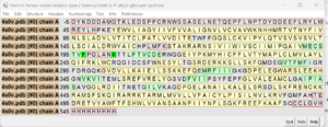
this box shows the sequence of amino acids in your structure.
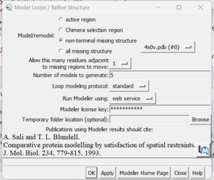
The second box is the important one for this step. This has the required inputs you need to give Chimera so it can re-model the missing loops:
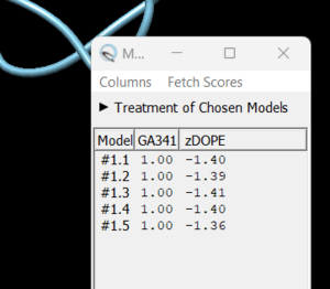
in this box choose 'non-terminal missing structure' and click 'Apply'. You can monitor the progress of Modeller in the lower left hand corner of the display. Once it has finished, another dialogue box will appear showing you the five choices of models for the missing sections.
As you click on each of the results, the re-created missing section will show up. Decide which one you want to keep, highlight it and save the file by choosing File → Save PDB. In the dialogue box, be sure to give this file a new name so as not to overwrite the original 4s0v.pdb file, something similar to 4s0v_loops_fixed.pdb. In the 'Save models' section, choose the model number you chose above. To confirm that everything has worked correctly, close your current session in Chimera and open 4s0v_loops_fixed.pdb. You should now see no dashed lines and only the structure with the re-created loops.
You are now ready to move onto preparing the ligand and protein structures for docking.
Preparing the Protein file
The first step in preparing the protein is to get the protein structure alone in a .pdb file. To do this:
- Select an atom on the protein
- Press the up arrow until the entire protein is selected
- Go to Select → Invert (all models). This will change the selection from the protein to everything else in the structure
- Go to Actions → Atoms/Bonds → Delete
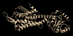
- Save the structure with a new file name (i.e. 4s0v_protein_only.pdb). Your pdb file will now look similar to this:
At this point we also need to generate a .mol2 file for the structure in this state. Go to File → Save Mol2 and give the file a descriptive name such as 4s0v_protein_no_hydrogens_no_charges.mol2
There are now two more steps necessary for its preparation:
- Adding hydrogens
- Adding charge
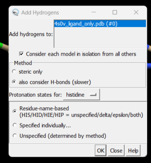
To add hydrogen atoms click on: Tools → Structure Editing → AddH. This command will cause the following dialogue box to appear:
Click 'OK'. When the program is finished, the bottom left-hand side will say "Hydrogens added" but you won't see any change in the structure. It's good practice to make sure that the program worked properly by showing the atoms at a small area of the protein and ensuring hydrogens were added. To do with we're going to use the 'zone' command which is quite useful:
- Click on one atom anywhere on the protein
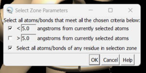
- Click on Select → Zone. This will cause the following dialogue box to appear:
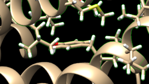
make sure to click the same options as shown above and click on 'OK'. Go to Actions → Atoms/Bonds → show and the atoms in the atoms in the selected area will be shown. If the hydrogen atoms were successfully added you'll see structure similar to:
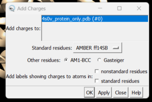
and you can see the white ends to the atoms which are the hydrogens. The final step is to add charges to the protein. Before you do this you should clear your selection by clicking on Select → Clear Selection. To add charges click on Tools → Structure Editing → Add Charge and the following dialogue box will show up:
Click on 'OK' and once the program is finished the bottom left hand corner will tell you what the total charge of the structure is. This number should be an integer. Your protein structure is now completely prepped and ready for docking. The final step is to save two files, a .pdb of the structure in this state and a .mol2 file. Simply go to File → Save PDB and choose a filename such as 4s0v_charges.pdb; then go to File → Save Mol2 and choose a filename such as 4s0v_protein_with_charges.mol2.
Preparing the Ligand File
The first step in preparing the ligand is the same as for the protein - we need to get the ligand structure alone in a .pdb file. To do this:
- Select an atom on the ligand
- Press the up arrow until the entire ligand is selected (you may have to press the up arrow many times)
- Go to Select → Invert (all models). This will change the selection from the ligand to everything else in the structure
- Go to Actions → Atom/Bonds → Delete
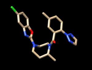
- Save the structure with a new file name (i.e. 4s0v_ligand_only.pdb). The image will look similar to this:
Before we start preparing the ligand for docking we need to again save a .mol2 file for the structure in this state. Go to File → Save Mol2 and give the file a descriptive name such as 4s0v_no_hydrogens_no_charges.mol2
Once we have the ligand saved as its own file we follow the same two steps we did for the protein:
- Add hydrogens
- Add charges
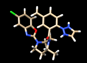
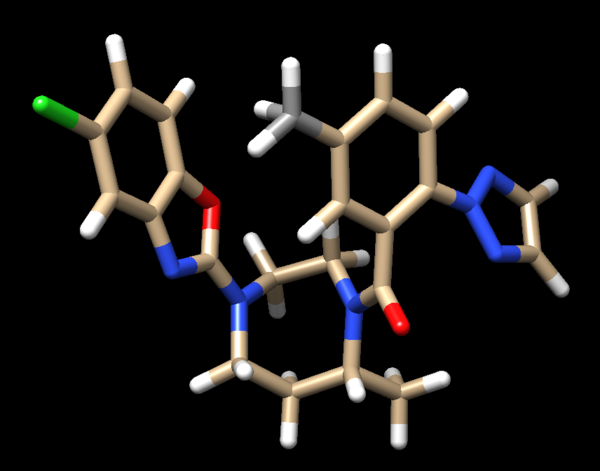
These steps are a bit more complicated for the ligand because Chimera may have mistakes and we need to do our best to determine where hydrogens should be, what the overall charge of the ligand is, and what changes we need to make to the results presented by Chimera. Once the hydrogens are added to the ligand your file should be similar to:
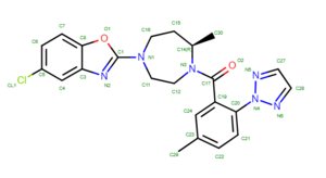
To determine if Chimera added hydrogens to the correct location we should look at the 2D structure of the ligand. This can be found on the pdb page where we downloaded the .pdb file.
clicking on the 2D image of the ligand brings up an enlarged image:
Another useful tip is to google the compound name of the ligand to try and find structures of it to compare against.
Once you have these two references, you'll want to start with the carbon atoms. We see on C29 there are 2 hydrogens but this should really be a methyl group (3 hydrogens). To fix this:
- select both hydrogens bonded to C29
- Actions → Atom/Bonds → Delete
- Select the carbon atom from which you just deleted the two hydrogens
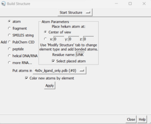
- Tools → Surface Editing → Build Structure (the following dialogue box will appear):
- In the top drop down, change from 'Start Structure' to 'Modify Structure'
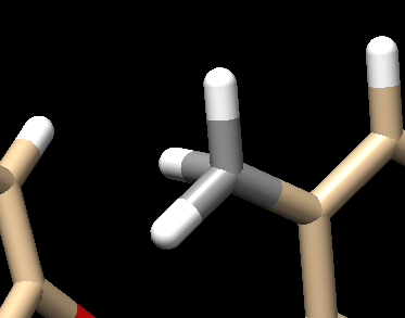
- Ensure the element says 'C' for carbon, and choose 4 bonds (since we want this carbon to have three hydrogens as opposed to the 2 hydrogens that Chimera gave it).
- Click 'Apply'
Your structure should now show a methyl group:
Next look at the oxygen atoms and do the same thing in determining if the protonation state of each is correct. For this structure it is, so we can move onto examining the nitrogen atoms. This is a bit trickier and it's not always obvious what the protonation state should be. A good way to determine this is to look at the original pdb file, with both the ligand and protein, with hydrogens added and determine if there are any interactions that don't seems right. To do this:
- Close your current session
- Open the original pdb that was downloaded
- Add hydrogens following the steps outlines above
- Look for interactions
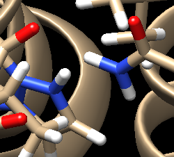
For the complex 4s0v, we see the following interaction that doesn't make sense:
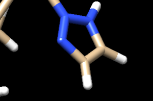
We see two hydrogens very close to each other. Hydrogens are positively charged so, in nature, if two were this close to each other they would repel each other, which isn't happening if the ligand is tightly bound to the protein. What we need to do is remove the hydrogen the Chimera put on the ligand. Hover your mouse over the hydrogen on the ligand, note it's number, and close the session. Open your ligand only file and select the hydrogen in question. Once the hydrogen is selected, go to Actions → Atom/Bonds → Delete which will delete the hydrogen we don't believe belongs there. Our ligand now looks like:
Looking at the ligand further we determined that the second hydrogen on the opposite nitrogen also didn't belong so that one was also removed. This is the final change we need to make to the ligand structure which now looks like this:
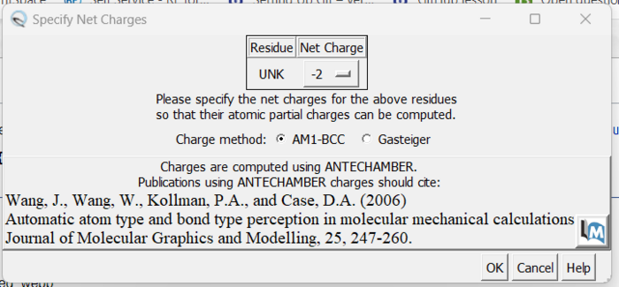
The final step is to add charges to the ligand. We follow the same steps as for the protein except after the dialogue box appear and we click 'OK', a second box will appear:
Here a knowledge of organic chemistry will be needed. Chimera sees that we removed two hydrogens so expects the ligand charge to be -2 but the overall charge of the ligand should be 0. Simply make this change in the drop down and click 'OK'. When the program is completed, you see the total charge calculated for the ligand in the lower left hand corner. This number should be an integer (or close to it). We are now done prep'ing the ligand for docking.
The final step is to again save two files, a .pdb and .mol2 of the structure in this state. Go to File → Save Mol2 and give the file a name such as 4s0v_ligand_hydrogens_charges.mol2 and File → Save PDB and give the file a name such as 4s0v_ligand_hydrogens_charges.pdb.
Final Steps
Before moving onto finding the binding site of the protein we need to move the four .mol2 files over to Seawulf. Do this using the following scp command:
scp *.mol2 username@login.seawulf.stonybrook.edu:'/gpfs/projects/AMS536/YOURYEAR/students/YOURGROUP'
Creating the Protein Binding Site Surface
This section will walk you through the steps necessary to identify the binding site of the protein using a function within DOCK to place surface spheres along the protein.
Creating the Required Surface (DMS) File
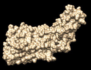
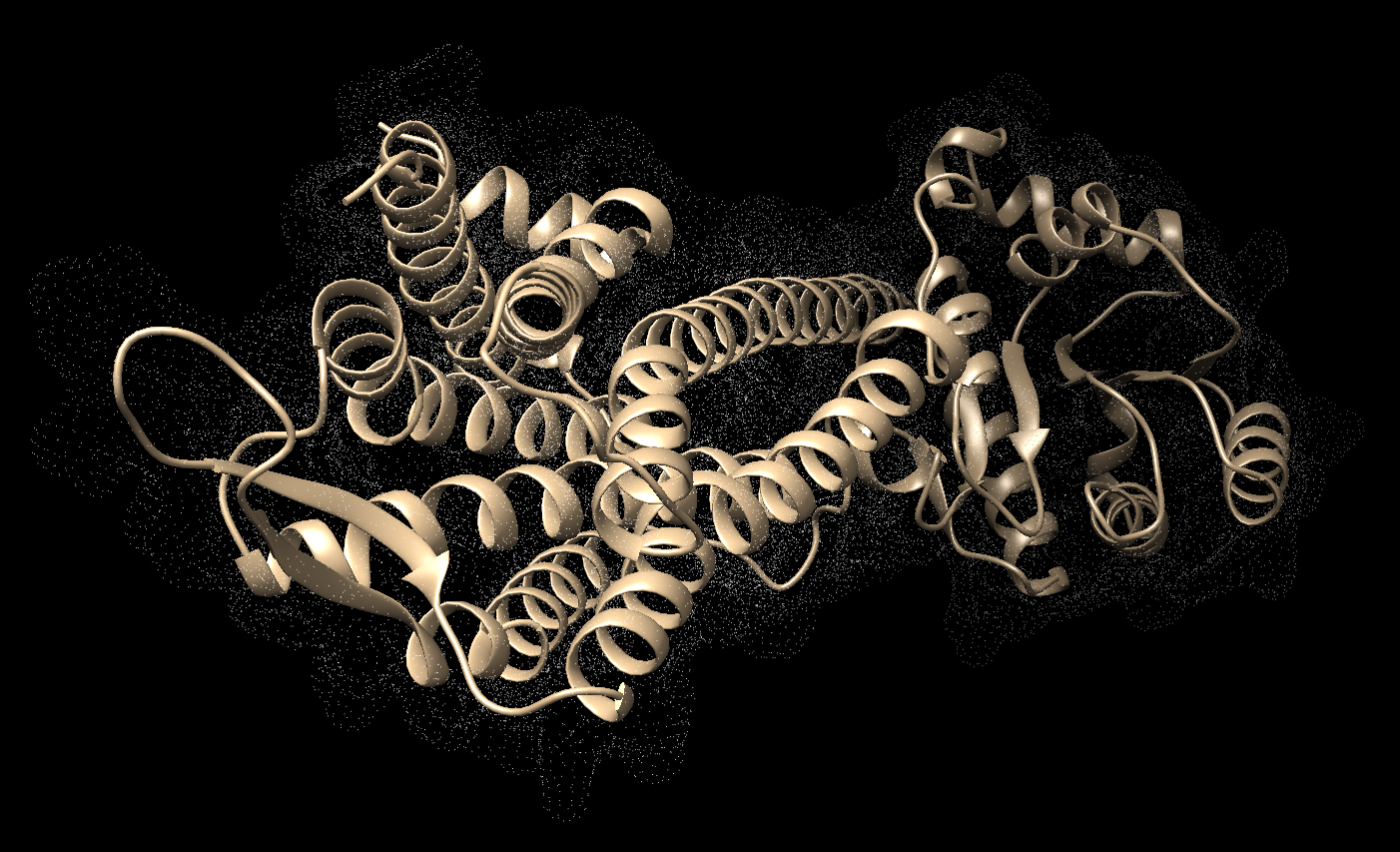
In Chimera, open the 4s0v_protein_only.pdb file. Go to Actions → Surface → show. This will display the van der Waals surface of your protein. Your image should be similar to:
Once this is done the .dms file needs to be generated by clicking on Tools → Surface Editing → Write DMS. A dialogue box will appear where you need to give the file a name, such as 4s0v_surface.dms. Once this file is saved, we need to make sure that nothing was unintended happened with DOCK during its generation. We do this by overlaying the .dms file with the protein_only file. To do this, close your current session, open the 4s0v_protein_only.pdb and then open the 4s0v_surface.dms. If everything worked as it should you should see an image similar to:
As you can see, the small dots (which is the .dms file) is perfectly aligned over the protein structure. Now that we have verified that everything looks good, we can continue.
Generating Spheres for the Binding Site
Now that we have a .dms file, we need to find the binding site of the protein using a DOCK program called sphgen. This program is run on the command line on Seawulf. In order for it to run properly you need to scp the .dms file to the 002.surface_spheres directory using the command:
scp filename.dms username@login.seawulf.stonybrook.edu:'/gpfs/projects/AMS536/YOURYEAR/students/YOURGROUP/002.surface_spheres'
Once the file is in your 002.surface_spheres directory you need to create a file to run sphgen. Type:
vi INSPH
this will open a new text document with the name INSPH. Put the following in the document replacing the filenames with your specific files:
 4s0v_new_surface.dms
 R
 X
 0.0
 4.0
 1.4
 4s0v_binding_spheres.sph
Note that the first and last lines need to be updated to be the name of your files. Save this file and return to the command line using the command:
sphgen -i INSPH -o OUTSPH
When this is completed you will see the 4sv0_binding_spheres.sph in your directory. Once again we need to verify that this file was generated properly. Do this by comparing it to the original .pdb. Using scp, move the output file (in this case 4s0v_binding_spheres.sph) back to your local computer and open the file in a new Chimera session. In the same session, open the original .pdb file and the two structures should be aligned to each other. Your image should be similar to:
As you can see, the ribbon of the original file is aligned to the spheres we just generated. At this point we can move onto the next step of selecting the spheres within the binding site of the protein.
Binding Site Spheres
This step runs a DOCK program called sphere_selector which is again run on the command line. Log back in to Seawulf and move to your 002.surface_spheres directory. Then type:
sphere_selector 4s0v_binding_spheres.sph ../001.structure/4s0v_ligand_hydrogens_charges.mol2 10.0
When this program has successfully completed you'll see a new file in your directory called selected_spheres.sph. This file generated spheres which should line up with the binding site of the protein. We need to verify this in Chimera:
- scp selected_spheres.sph to your local computer
- Close any open sessions you have in Chimera
- In Chimera open selected_spheres.sph
- In the current session, open the original protein/ligand complex (4s0v.pdb)
- You should see the spheres located within the binding site of the protein, similar to:
While this looks good we should verify that the spheres are actually where the ligand is. Let's do this by selecting the spheres, hiding them from view, and verifying the ligand is in the same location:
- Hold down ctrl and click on a sphere
- Press the up arrow until all spheres are selected
- Actions → Atoms/Bonds → hide
- Verify the ligand is where the spheres were
and we see the ligand is where the spheres were so we can be confident in our work so far.
Box and Grid Generation
The next step in the docking process is to generate energy interactions between the atoms of the protein and ligand. If this was done for the whole complex it would take too long to run to be useful. To get around this computationally expensive step, dock uses a box/grid method. We will define a box around the area of interest for the protein/ligand and DOCK will generate a grid within this box which will be used in the energy calculations.
Generating the Box
To generate the box we will be working again on the command line using a DOCK program called showbox. Start by logging into Seawulf and navigating to your 003.gridbox directory. We need to make a new file called showbox.in by typing:
vi showbox.in
This will create a new file, with a filename of showbox.in and open it in vi. The following commands need to be typed:
     Y
     8.0
     ../002.surface_spheres/selected_spheres.sph
     1
     4s0v.box.pdb
Remember to change the last line to be a filename with the number of protein you are working with. The second line of this code (8.0) is telling dock how many angstroms from the selected spheres to draw the box. Depending on your system you may need to modify this number.
To run this file, simply type:
showbox < showbox.in
If showbox was successful the file 4s0v.box.pdb will now be in your directory.
Generating the Grid
Now that we have our box defined we need to instruct DOCK to generate the grid within it. We do this using a DOCK program called grid:
vi grid.in
This command will generate and open a file named grid.in. The commands to be typed into this file are:
   compute_grids                             yes
   grid_spacing                              0.4
   output_molecule                           no
   contact_score                             no
   energy_score                              yes
   energy_cutoff_distance                    9999
   atom_model                                a
   attractive_exponent                       6
   repulsive_exponent                        9
   distance_dielectric                       yes
   dielectric_factor                         4.
   bump_filter                               yes
   bump_overlap                              0.75
   receptor_file                              ../001.structure/4s0v_protein_hydrogens_charges.mol2
   box_file                                  4s0v.box.pdb
   vdw_definition_file                       /gpfs/projects/AMS536/zzz.programs/dock6.9_release/parameters/vdw_AMBER_parm99.defn
   score_grid_prefix                         grid
The only change you need to make to the above commands is the receptor_file and box_file to reflect the files you previously generated.
Once this file is saved, run it:
grid -i grid.in -o 4s0vGridInfo.out
Be patient, this step might take a few minutes to run. You will know it's worked successfully if you see:
- grid.bmp
- grid.nrg
- 4s0vGridInfo.out
in your directory. With the box and grid successfully generated we are ready to move onto the energy minimization step.
